To begin working with open-source tools for CMOS analog IC design, all you need is a computer and a stable internet connection.
It is recommended to install Linux, as all of the essential tools run smoothly on Linux-based systems. Linux distributions are free, and if you are using Windows, you can easily set up a Linux environment through WSL (Windows Subsystem for Linux). For example, I am using Ubuntu on WSL.
Below are the main tools used in a typical analog IC design flow:
In this article, we extract the small-signal characteristics of MOSFETs using open-source and free available PDKs and CAD tools. The analysis is carried out using the SkyWater sky130 PDK, Xschem as the schematic capture tool, and Ngspice as the circuit simulator.
All tools (Xschem, Ngfspice, and sky130 PDK) must be installed properly on a Linux system. In this work, Ubuntu running under WSL is used. The installation procedure is discussed in a separate article.
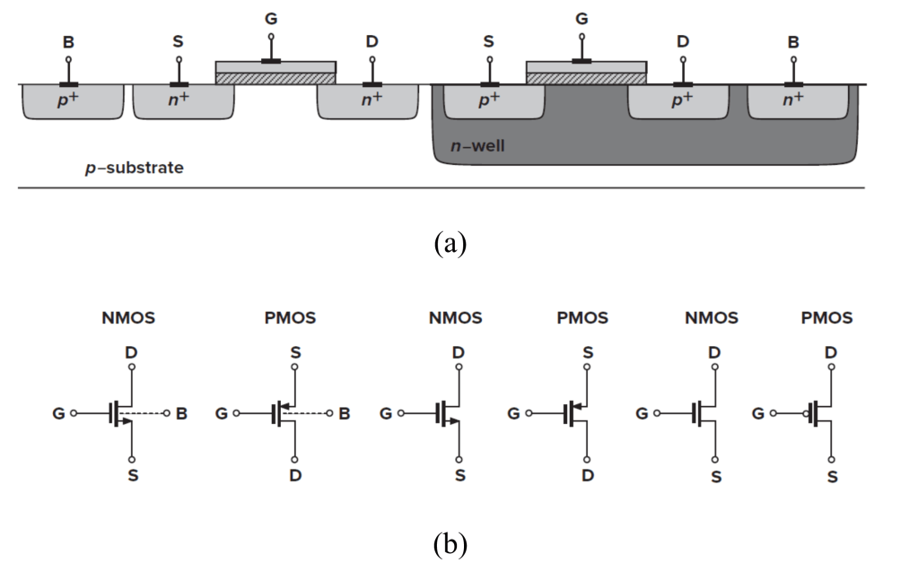
The reader is assumed to have a basic understanding of MOSFET device physics and the fundamentals of MOSFET operation. Figure 1 illustrates the structure and symbols of NMOS and PMOS devices. In integrated-circuit design, each MOSFET has four terminals: gate (G), source (S), drain (D), and bulk (B). Modern CMOS technologies typically employ a p-type substrate; therefore, the bulk of all NMOS devices (except native devices) is tied to the substrate, i.e., GND or VSS. In contrast, PMOS devices are fabricated in isolated wells, allowing their bulks to be biased independently.
Figure 1: (a) structure of NMOS and PMOS, (b) symbols (from [1])
Operation regions:
A MOSFET behaves as a switch (ON or OFF) in digital design, but in analog design it operates in one of three regions:
Cut-off (OFF): VGS < VTH and VGD < 0
Saturation: VGS > VTH and VGD < VTH
Triode (ON): VGS > VTH and VGD > VTH
Note that the transition between these regions is smooth, especially near the threshold voltage.
Voltage – Current Characteristics:
To explain MOSFET operation, we review the V–I equations of an NMOS transistor. PMOS equations follow the same form.
Triode region (ON):
For VDS << 2(VGS – VTH):
Saturation region:
Including channel length modulation,
The parameter λ is the channel-length modulation coefficient, which decreases with increasing channel length:
Second-order effects:
Body effect: Increasing the source-to-bulk voltage raises the threshold voltage:
Subthreshold (Weak Inversion) : When VGS ≈ VTH, the device enters weak inversion, and the drain current follows:
where I0 is proportional to W/L, and ξ > 1 and VT = kT/q. We say the device operates in weak inversion in contrast with strong inversion.
Small-signal model:
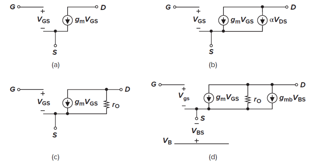
Fig.2 shows the small-signal MOSFET model [1].
Figure 2: (a) Basic MOS small-signal model; (b) channel-length modulation represented by a dependent current source; (c) channel-length modulation represented by a resistor; (d) body effect represented by a dependent current source. [1]
Equations:
In triode region, a MOSFET behaves as a voltage-controlled resistor:
In saturation, the transconductance is:
Equivalent expressions include:
The output resistance due to channel-length modulation is:
For λVDS << 1,
The body-effect transconductance is:
where η is typically around 0.25
Simulation results:
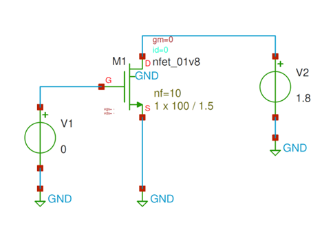
Long-channel NMOS: The circuit in fig. 3 is used to evaluate the small-signal, low frequency behavior of an NMOS device. Because capacitances are not considered in this section, DC-sweep analysis is employed.
Figure 3: Simple NMOS circuit used for DC-sweep analysis
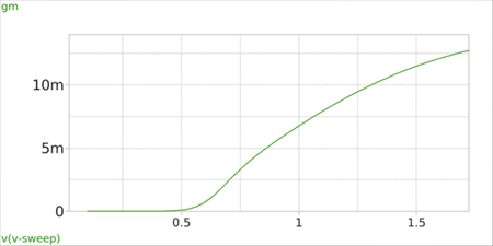
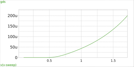
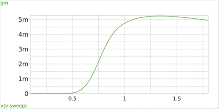
Here, the W/L is 100u/1.5u, number of gates (fingers) are 10, and the VGS sweep is from 0 to 1.8V. Fig. 4 shows gm and gds of the NMOS versus VGS.
Figure 4(a)Figure 4(b)
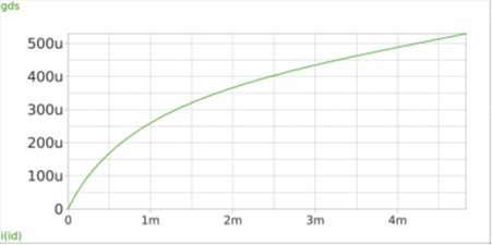
In this circuit, VTH ≈ 560mv. As expected, by increasing VGS, both gm and gds increase. It’s interesting to see the gds – ID relationship as shown in fig. 5. The curve is nearly linear, and according to (15), its slope is corresponds to the channel-length modulation coefficient λ.
Figure 5: gds vs. ID
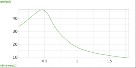
The intrinsic small-signal gain of a MOSFET is defined as
Fig. 6 plots the gain vs. VGS.
Figure 6: Intrinsic small-signal low-frequency gain of NMOS with W/L = 100u/1.5u
In this example of long-channel NMOS, the gain peaks at an overdrive voltage of Vov = VGS – VTH ≈ 100 mV.
As Vov (and thus ID) increases, the gain decreases. Below Vov ≈ 80 mV, the device is in weak inversion, and for VGS < VTH, the gain loses its physical meaning.
Short-channel (sub-micron) NMOS: For channel length below 1 um (sub-micron), the MOS device behavior is significantly affected by short-channel and higher-order effects. Figure 7 illustrates how these phenomena alter the small-signal parameters for a device with W/L = 10u/0.15u. Detailed discussion of short-channel devices will be provided in a subsequent article.
Figure 7(a)Figure 7(b)Figure 7(c)Figure 7(d)
[1] Razavi, B., Design of Analog CMOS Integrated Circuits, 2nd ed. New York, NY, USA: McGraw-Hill, 2017.
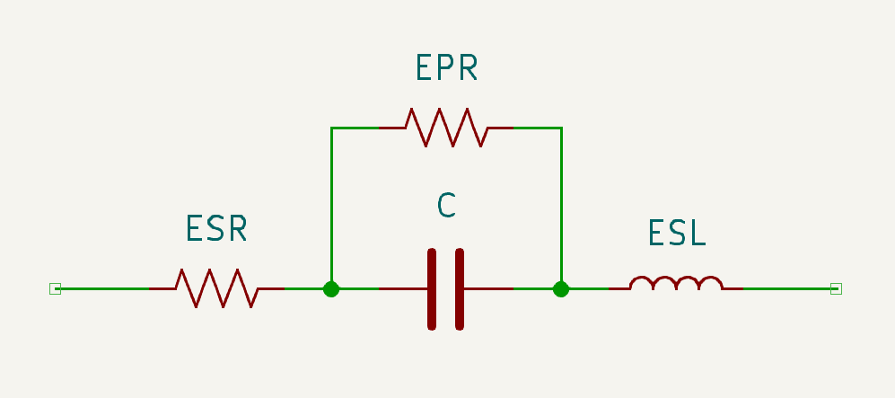
A capacitor doesn’t always behave like a capacitor, especially at high frequencies. As shown below, the equivalent circuit of a capacitor includes a series inductance, known as the Equivalent Series Inductance (ESL). The ESL varies depending on the capacitor type, packaging, and physical dimensions.
Capacitor Model
At low frequencies, the impedance of the ESL (ZL) is negligible compared to the impedance of the capacitor (ZC):
As the frequency increases, ZL increases while ZC decreases. At high frequencies, the inductive impedance dominates, causing the capacitor to act more like an inductor. But what do we mean by “low frequency” and “high frequency”? How can they be distinguished?
At a specific frequency, the two impedances ZL and ZC become equal. This is known as the self-resonant frequency (SRF) of the capacitor:
Larger capacitors tend to have a lower SRF. This is why, in some cases, you may see a nano-Farad capacitor placed in parallel with a multi-micro-Farad capacitor. The smaller capacitor is used to maintain capacitive behavior at higher frequencies where the larger capacitor cannot.
Capacitor is a basic and one of the most important components in electronics.
Capacitors come in various types, each suited for specific applications. Here are some common types of capacitors:
Ceramic Capacitors: Widely used in electronic circuits for their small size and stability. They come in various temperature coefficients and voltage ratings.
Electrolytic Capacitors: Typically used for power supply filtering and energy storage due to their large capacitance values. They are polarized and have higher capacitance per unit volume compared to ceramic capacitors.
Tantalum Capacitors: Similar to electrolytic capacitors but offer better performance in terms of stability and reliability. They are also polarized and used in applications requiring high capacitance and low leakage current.
Film Capacitors: Known for their high precision, stability, and low loss. They are used in applications where a stable and reliable capacitor is required, such as in audio equipment and power electronics.
Supercapacitors (Ultracapacitors): Offer very high capacitance values and can store large amounts of energy. They are used in applications requiring rapid charge and discharge cycles, such as in energy storage systems and backup power supplies.
Mica Capacitors: Provide high precision and stability, often used in RF and microwave applications due to their low loss and high-frequency performance.
Polymer Capacitors: Similar to electrolytic capacitors but use a solid polymer electrolyte. They offer better performance in terms of ESR (Equivalent Series Resistance) and stability.
Variable Capacitors: Allow adjustment of capacitance value, commonly used in tuning circuits for radios and other communication devices.
Each type of capacitor has its unique characteristics and is chosen based on the specific requirements of the application.
ESR:
ESR (Equivalent Series Resistance) is an important characteristic of capacitors. In some applications like switching-mode power supplies (SMPS) this parameter plays a critical role to select the capacitor.
The capacitor model is shown below.
Capacitor model
Some manufacturers produce capacitors specifically for low-ESR. The specifications of Low-ESR Series can be found in data sheets published by manufacturers. The table below shows some popular Low-ESR series of capacitors.
Manufacturer
Series
Style
Technology
Low ESR down to [mΩ @ 20ºC / 100kHz
AVX
TCJ
Chip
Polymer aluminium
10
AVX
TCQ
Chip
Polymer aluminium
25
AVX
TCM
Chip
Polymer tantalum multi-anode
6
AVX
TPS
Chip
Tantalum
25
AVX
TPM
Chip
Tantalum
12
KEMET
A700
Chip
Polymer aluminium
4.5
KEMET
A759
Radial
Polymer aluminium
12
KEMET
A768
SMD
Polymer aluminium
15
KEMET
T528
Chip
Tantalum multi-anode
4
KEMET
T520/T530
Chip
Tantalum multi-anode
4
Murata
ECAS
Chip
Polymer aluminium
6
Nichicon
GYB
Chip
Aluminium electrolytic
20
Nichicon
GYC
Chip
Aluminium electrolytic
20
Nichicon
PCH
Chip
Aluminium electrolytic
13
Nichicon
PCR
Chip
Aluminium electrolytic
13
Nichicon
UCM
Chip
Aluminium electrolytic
50
Nichicon
UCZ
Chip
Aluminium electrolytic
32
Panasonic
FN
SMD
Aluminium electrolytic
80
Panasonic
FT
SMD
Aluminium electrolytic
60
Panasonic
FS
Radial
Aluminium electrolytic
12
Panasonic
OS-CON™
Chip
Polymer aluminium
14
Panasonic
SP-Cap
Chip
Polymer aluminium
6
Panasonic
ZA
SMD
Polymer hybrid
20
Panasonic
ZC
SMD
Polymer hybrid
20
Rubycon
ZLH
Radial
Aluminium electrolytic
12
Rubycon
PC-CON
Chip
Polymer aluminium
4.5
Vishay
190 RTL
Radial
Aluminium electrolytic
17
Vishay
170 RVZ
Radial
Aluminium electrolytic
17
popular Low-ESR series of capacitors in the market. (Source: avnet.com)
Resistor is a key component, especially in discrete Electronics. According to Ohm’s Law:
the voltage across resistor equals the current passes through the resistor times the resistance R.
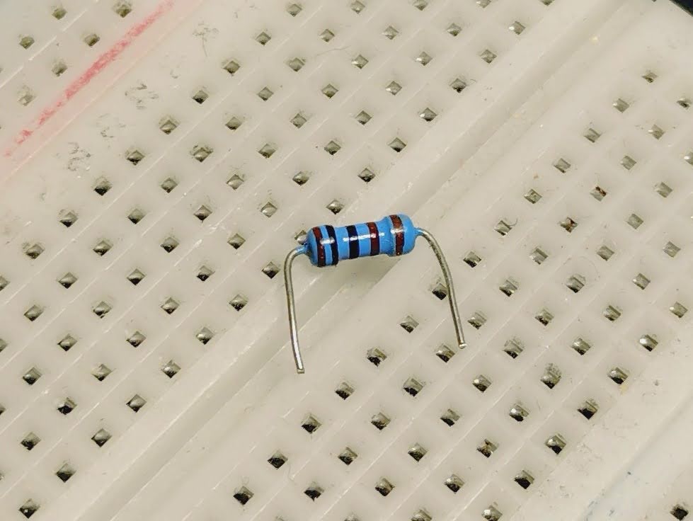
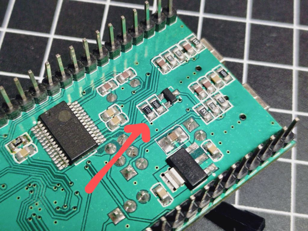
Regarding assembly, there are two types of packaging: 1. Through-hole 2. Surface-mount or SMD These two types are shown below.
Through-hole Resistor
Surface-mounted Resistor (SMD)
You can find a lot of data about resistors on the Internet. Here, some essential and useful information is collected.
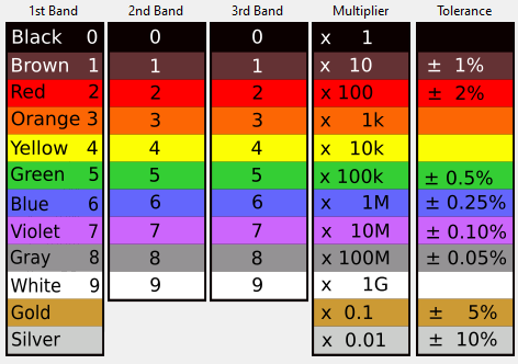
Colors:
To show the value of a through-hole resistor, usually color codes are used.
Resistor band colors. (Source: KiCad)
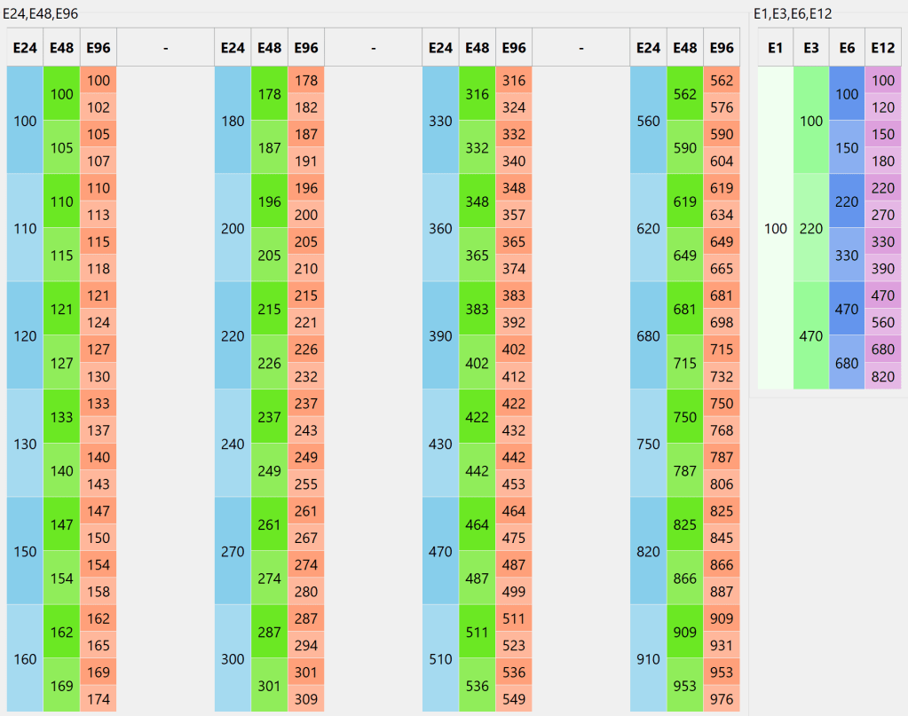
Tolerance:
Common tolerances of resistors are 5% and 1%. 5% resistors use E24 values and 1% resistors use E96 values. The E-series values table is shown below.
E-series values. (Source: KiCad)
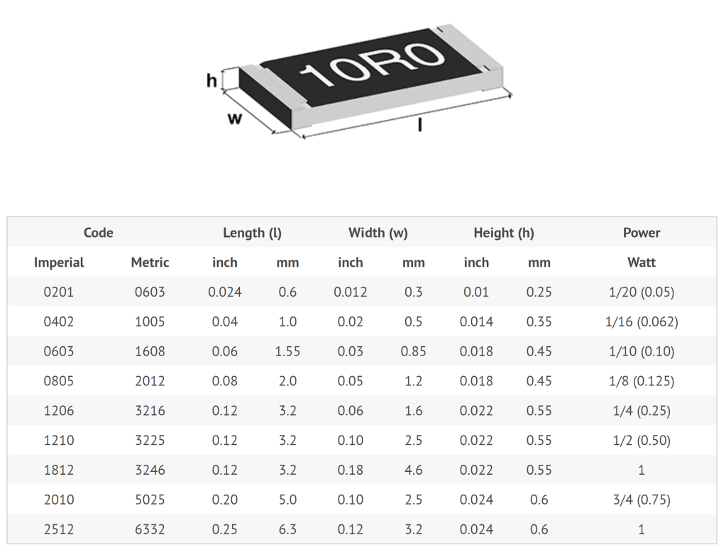
power Rating:
Both through-hole and SMD resistors provides various packaging size regarding power rating. below the package size info for TH and SMD are shown respectively.